Overview
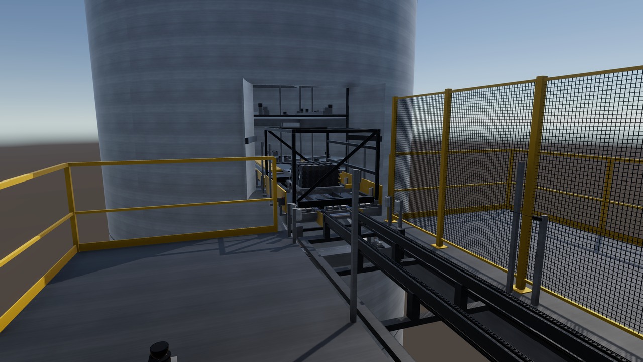
An elevator lifts each rack to the ship's door, where it is checked, pushed in and locked.
Area 19 is the last step of the export chain. A tower elevator lifts each rack to the side door of a cargo ship on the launch pad. One ship takes one cargo set: 26 racks with 49.0 t of net product.
The rail cart brings the racks in load-plan order. At the top, the rack stands on a scale, and its mass and radio tag are checked. A correct rack crosses a bridge into the bay, and four pins lock it in its slot.
Process steps
- The rail cart docks at the tower base with the next rack.
- A chain conveyor moves the rack into the elevator, and two clamps hold it.
- The elevator lifts the rack to the landing at the cargo door.
- The landing checks the mass within ± 1 % and reads the tag.
- A correct rack crosses the bridge into the bay. A wrong one goes back.
- The ship's lift sets the rack in its slot, and four pins lock it.
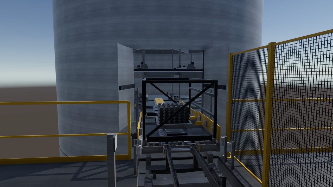
The line in the twin
Turning view
Specifications
The equipment list
| Unit | Function | Key data |
|---|---|---|
| Service tower elevator | Lifts one rack at a time to the cargo door. | Rated load 3,000 kg, up to 0.9 m/s |
| Chain transfers at base, car and landing | Move the rack from cart to elevator to bridge. | Three 1.5 kW drives, 0.2 m/s |
| Landing check scale and radio tag reader | Checks the mass and identity of each rack. | 4 load cells of 1 t, ± 1 % window |
| Access bridge | Spans the gap from the tower landing into the ship. | Rests on the tower, never on the ship |
| Ship door, entry rail and internal lift | Pull the rack in and set it in its slot. | 26 slots, 60 s from entry to slot |
| Slot lock | Locks the rack feet in the slot and confirms it. | 4 air-driven pins, lock confirmed within 5 s |
Links lead to the makers' public product pages and are given for reference only. This site is independent work, not affiliated with, sponsored or endorsed by any manufacturer. The makers are responsible for the content of their pages. Trademarks belong to their owners.
Control and safety
- Emergency stops, scanners and a light curtain (safety light beams) cut the drive power safely.
- A rack enters only with the right mass and tag, the bridge locked and the door open.
- Fault test cases are specified for six faults, such as a wrong rack order or an unconfirmed lock.
- The single devices are modelled from the datasheet and tested against the PLC, the industrial control computer.
The hand-overs
| From | Loaded racks come one at a time by rail cart from Area 18, in load-plan order. |
| To | Each ship gets 26 locked racks and a load table with each rack's mass and slot. |
The devices and signals
- One PLC with 31 input and output terminals in 2 I/O stations, at the base and at the landing.
- 118 signals: 39 digital inputs, 23 digital outputs, 5 analog, 30 safe inputs, 17 safe outputs and 4 others.
- 3 conveyor drives on hard-wired signals and 3 brake motors with safe brake control.
- The tower elevator is a machine with its own controller, used through its signals.
- Safety devices: 2 emergency stop stations, 3 outdoor safety laser scanners, 1 light curtain with muting at the car entry, 2 gates with guard locking and 2 coded safety sensors.
- Process sensors: a landing scale on 4 load cells and a radio tag read head.
The safety functions
- Emergency stop: safe torque off of the 3 conveyor drives and a safe stop of the elevator.
- The elevator stop circuit is opened by two safety contactors with feedback. The twin found that a 24 V safety output was planned straight into its 230 V circuit.
- Base scanner, a light curtain with muting at the car entry and a presence scanner in the car.
- Landing gate and bridge gate with guard locking: the bridge cannot rise during a push.
- Target: performance level d for all functions, a target and not a claim.
The tests run in the twin
- Scene built in 3D on 2026-11-02. Its probe: 21 checks passed, 1 failed (a support check).
- PLC program reviewed in 4 rounds, ready at round 4 on 2026-11-01.
- The first run against the 3D scene is the next step.
- Nine fault tests are defined, among them an emergency stop while the car moves and an opened bridge gate during a push.
About this page
In the scenario, this tower is where each cargo set leaves 16 Psyche for the Earth.
Real devices, built from real data
Every machine and device in this twin is a real industrial product from the makers' catalogues. They range from sensors, valves and drives to safety scanners, load cells and RFID readers. Each model is built from the product's published data: dimensions, sensing ranges, signals, rated values, parameters and timing.
The PLC programs use the devices' real interfaces and parameters. Before any hardware existed, the twin found hundreds of faults in the plant design and the programs. So a real commissioning would need fine tuning, not a redesign.