Overview
Two lines of dry magnetic drums pull the metal out of 8.40 t/h of crushed rock.
Area 12 turns crushed ore into metal concentrate, a product that is mostly metal. The metal is natural iron-nickel and mostly magnetic, while the rock is not. So drums with permanent magnets can pull the metal out, with no water and no chemistry.
Two lines work side by side, one for coarse and one for fine material. In each line, a rougher drum catches nearly all the metal with some rock. A cleaner drum then rejects most of that rock. Belts carry the concentrate to the bins.
Process steps
- Bins A and B receive the 3-12 mm and -3 mm fractions from crushing.
- A tray feeder under each bin doses the material onto its rougher drum.
- The rougher holds the metal on its turning shell, and the rock flies off.
- The cleaner drum rejects most of the rock that came with the metal.
- A screw conveyor returns these rejects to the rougher feed.
- Belts take the concentrate to bins C and F and the rock to aggregate.
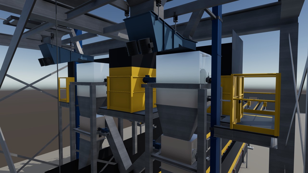
The line in the twin
Turning view
Specifications
The equipment list
| Unit | Function | Key data |
|---|---|---|
| Feed bins A and B | Buffer the two fractions from crushing. | 60 m³ each, radar level sensors |
| Vibratory tray feeders | Dose each fraction onto its rougher drum. | 5.20 t/h coarse, 3.20 t/h fines |
| Rougher magnetic drums | Catch nearly all the metal and throw off the rock. | Ø 500 x 1,000 mm, 45 rpm, 1.5 kW |
| Cleaner magnetic drums | Reject most of the rock left in the metal. | Ø 300 x 700 mm, 55 rpm, 1.5 kW |
| Concentrate belts with belt scales | Carry and weigh the coarse and fine concentrate. | 3.54 and 1.53 t/h, 500 mm belts |
| Return screw conveyors | Return the cleaner rejects to the rougher feed. | Ø 150 mm, about 0.59 and 0.38 t/h |
Links lead to the makers' public product pages and are given for reference only. This site is independent work, not affiliated with, sponsored or endorsed by any manufacturer. The makers are responsible for the content of their pages. Trademarks belong to their owners.
Control and safety
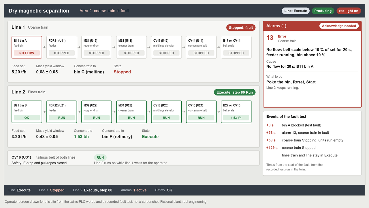
- Each line is designed separately, so a blocked bin or a stopped drum stops only that line.
- Every 60 s, the PLC (control computer) checks concentrate against feed and adjusts a splitter plate if needed.
- Emergency stops and safety ropes cut the motor power, and eight fault test cases are specified.
- The single devices are modelled from the datasheet and tested against the PLC.
The hand-overs
| From | From crushing: 3-12 mm (5.20 t/h) into bin A, -3 mm (3.20 t/h) into bin B. |
| To | Concentrate: 3.54 t/h to melting, 1.53 t/h to the refinery. Rock: 3.33 t/h to aggregate. |
The devices and signals
- One line PLC with 26 input and output terminals in 1 I/O station.
- 83 signals: 24 digital inputs, 16 digital outputs, 12 analog, 9 safe inputs, 4 safe outputs, 9 speed counters, 8 digital sensor ports and 1 power feed.
- 9 variable speed drives on hard-wired signals and 2 elevator motors on contactors.
- Safety devices: 1 emergency stop station, 3 pull-rope switches and a safe reset button.
- Process sensors: 2 belt scales, 2 radar level sensors, 4 vibration sensors, 9 speed sensors and 2 radio tag read heads.
The safety functions
- Emergency stop and pull-ropes: the drives ramp down for 3 s, then safe torque off after 4 s (stop category 1). The elevator motors stop at once (stop category 0).
- A fault in the safety group removes all safe outputs at once (stop category 0).
- Contactor monitoring: a welded contactor blocks the restart.
- Restart interlock: the safety logic reads the reset button itself. A release never starts anything. A new start comes after a 5 s warning.
- Fixed guards: 1,495 guard parts in the scene.
- Target: performance level d, a target and not a claim.
The tests run in the twin
- Closed on 2026-10-19 after the acceptance: 401 test rows, 380 passed, 0 failed, 21 not run by design.
- The first acceptance run was not accepted: 307 passed, 18 failed. The program was fixed and the second run passed.
- All eight fault test cases were run in the twin.
- After the acceptance, 534 of 534 PLC unit tests passed with the final overlay fix.
About this page
In the scenario, this area on 16 Psyche gives the furnaces clean metal, and the rock stays on site as building material.
Real devices, built from real data
Every machine and device in this twin is a real industrial product from the makers' catalogues. They range from sensors, valves and drives to safety scanners, load cells and RFID readers. Each model is built from the product's published data: dimensions, sensing ranges, signals, rated values, parameters and timing.
The PLC programs use the devices' real interfaces and parameters. Before any hardware existed, the twin found hundreds of faults in the plant design and the programs. So a real commissioning would need fine tuning, not a redesign.