Overview
Left-over rock, dust and furnace slag become aggregate (sorted stone material) and concrete blocks for the site.
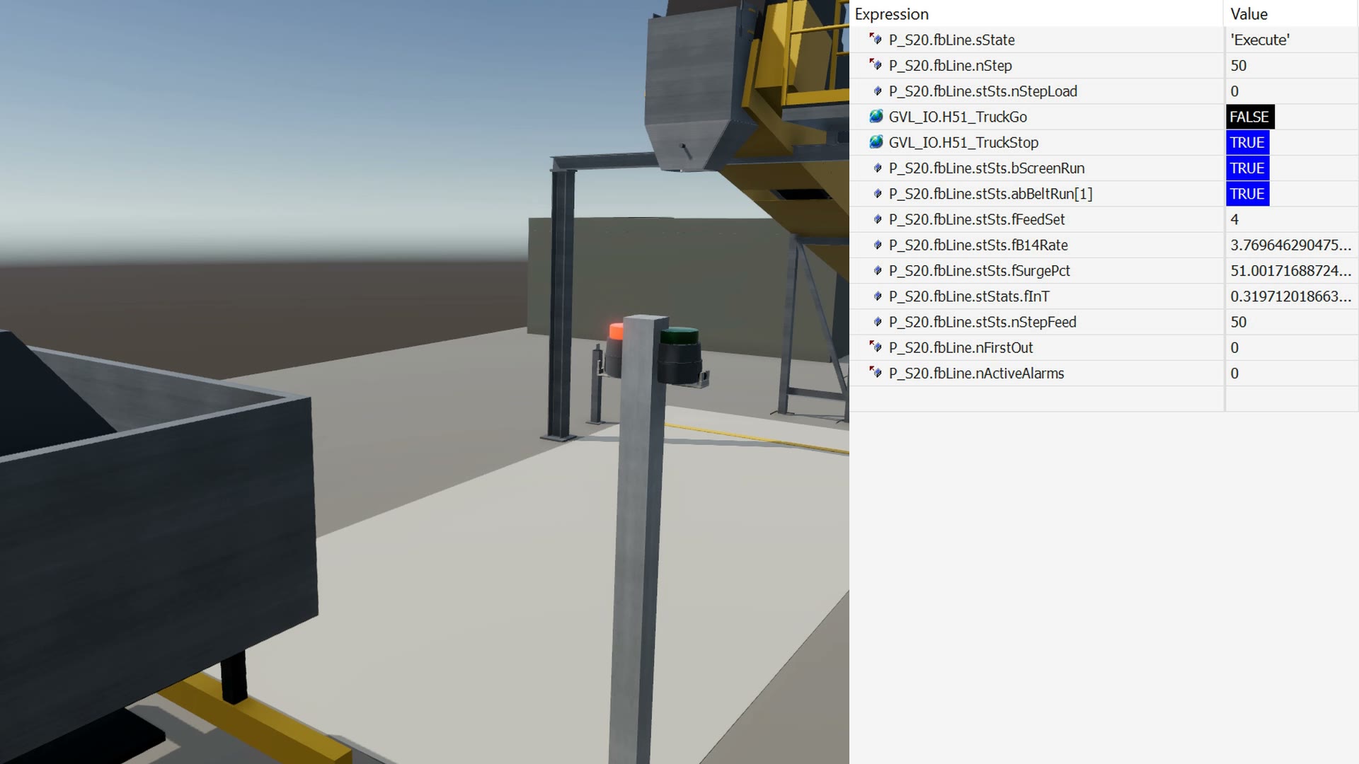
Area 20 is the by-product line. The plant ships only metal, and everything else stays on site as building material. The line takes 3.83 t/h of left-over rock, dust and slag and makes aggregate in three sizes and hollow concrete blocks.
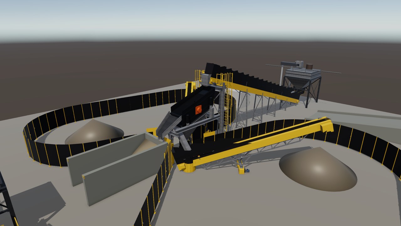
A feeder doses the material onto a vibrating screen, which sorts it into 0-4, 4-16 and 16-40 mm. Stackers build the piles, and site trucks are loaded to a set weight. Part of the material is mixed with binder and pressed into blocks.
Process steps
- Four by-product streams meet in a buffer bin.
- A belt feeder doses 2 to 6 t/h, set by the bin level.
- A vibrating screen sorts the flow into 0-4, 4-16 and 16-40 mm.
- Two swinging stackers build the piles and move to a new pile when full.
- A wheel loader fills the truck loadout, which loads trucks to a set weight.
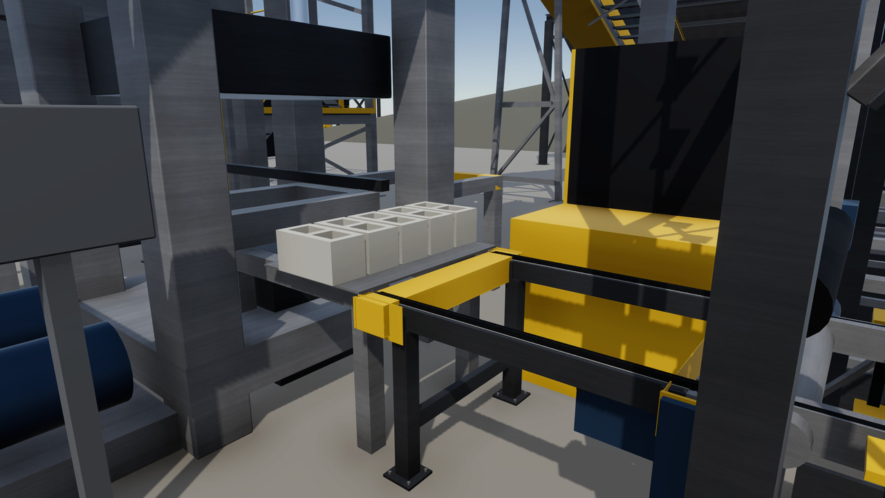
- The block line mixes aggregate and binder and presses five blocks every 20 s.
The line in the twin
Turning view
Specifications
The equipment list
| Unit | Function | Key data |
|---|---|---|
| Buffer bin with belt feeder | Collects the four streams and doses them to the screen. | Target 4.0 t/h, range 2 to 6 t/h |
| Inclined vibrating screen | Sorts the feed into three aggregate sizes. | Two screen decks, at 16 and 4 mm |
| Radial stackers | Swinging belt conveyors that build two piles each. | 0-4 mm 2.13 t/h, 4-16 mm 1.59 t/h |
| Truck loadout with belt scale | Loads trucks to a set weight and issues a ticket. | Up to 30 t/h, 10 t in about 20 min |
| Mixer and block making machine | Mix the concrete and press it into hollow blocks. | 0.90 t per batch, 5 blocks every 20 s |
| Curing rack and cuber | Hold fresh blocks to harden, then stack cubes of 50. | 144 boards, 8 h hardening, about 1.0 t per cube |
Links lead to the makers' public product pages and are given for reference only. This site is independent work, not affiliated with, sponsored or endorsed by any manufacturer. The makers are responsible for the content of their pages. Trademarks belong to their owners.
Control and safety
- One PLC (industrial control computer) is designed to run the line, steered by bin and pile levels.
- Emergency stops and pull-ropes along every belt cut the drive power safely.
- Fault test cases are specified for six faults, such as a full pile or a blocked chute.
- The single devices are modelled from the datasheet and tested against the PLC.
The hand-overs
| From | Four streams, 3.83 t/h: left-over rock from separation and refinery, crushing dust and furnace slag. |
| To | Aggregate goes by truck to base construction, blocks to the block yard. Nothing leaves the site. |
The devices and signals
- One line PLC with 47 input and output terminals in 2 I/O stations.
- 232 signals: 32 digital inputs, 41 digital outputs, 14 analog, 114 safe inputs, 16 safe outputs and 15 others.
- 12 drives: the screen drive on the fieldbus and 11 on hard-wired signals.
- Safety devices: 28 emergency stop stations, 3 pull-rope switches and 6 gate circuits with guard locking.
- Process sensors: 3 belt scales, 6 radar level sensors and 3 belt drift switches.
- Mixer, block machine, curing rack and cuber are machines with their own control.
The safety functions
- Emergency stop: safe torque off of both drive groups and the machine contactors off (stop category 0).
- Pull-rope switches along every walkway stop their drive group. A switch latches and needs a local reset.
- Board loop area: a 2.0 m fence with 8 gates, guard locking until the block unit stops, an escape lever inside, 10 inside emergency stops and a two-stage reset.
- Closed stacker zone: doors with guard locking; entry only after both stackers stop.
- A safe air dump valve holds the five transfer lifts. A reset never starts a belt.
- Target: performance level d, a target and not a claim.
The tests run in the twin
- First test rounds against the PLC since 2026-10-27.
- Window 2 (2026-10-27): 617 unit test checks, 598 passed, 19 failed. Twin rows: 33 passed, 6 failed.
- Window 3 (2026-10-31): the offline checks passed, with a scene self-test of 378 passed and 1 failed. The live steps wait.
- Six fault tests are defined, among them an emergency stop during truck loading and a stuck rope switch channel.
In the process chain
About this page
In the scenario, the rock freed from the metal stays on 16 Psyche and builds the next phase of the base.
Real devices, built from real data
Every machine and device in this twin is a real industrial product from the makers' catalogues. They range from sensors, valves and drives to safety scanners, load cells and RFID readers. Each model is built from the product's published data: dimensions, sensing ranges, signals, rated values, parameters and timing.
The PLC programs use the devices' real interfaces and parameters. Before any hardware existed, the twin found hundreds of faults in the plant design and the programs. So a real commissioning would need fine tuning, not a redesign.