Overview
A chain casting machine turns liquid metal into 20.7 kg ingots, each weighed and marked.
Area 14 casts liquid iron-nickel into 20.7 kg ingots. A chain casting machine carries a slow loop of 76 cast-iron moulds under water sprays. The solid ingots drop out at the end. A mark on each ingot traces it to its heat, the furnace batch.
A ladle from melting pours 3 t of metal into a pouring box. A stopper (a plug) opens once per mould, so one mould fills every 6 seconds. The ingots cool below 150 °C. Each one is weighed, and the good ones are marked.
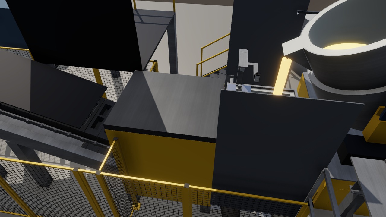
Process steps
- The ladle car is locked in place, and a tag reader checks the heat.
- The ladle tilts, and the stopper fills one moving mould every 6 seconds.
- Water sprays cool the moulds, and the ingots drop out at about 600 °C.
- A cooling conveyor with water mist and air brings them below 150 °C.
- A scale weighs each ingot, and ingots outside 19.5 to 22.0 kg are rejected.
- A marker stamps the heat and sequence number. A buffer feeds the bundling robot.
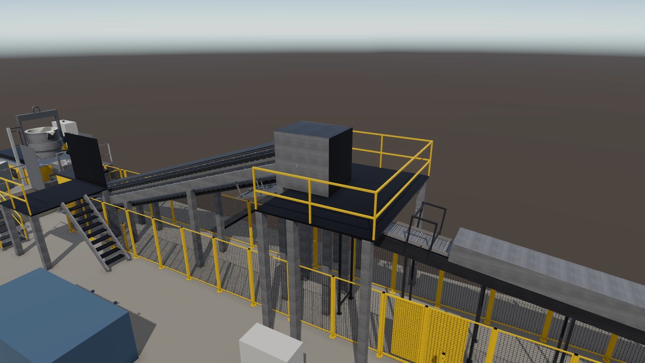
The line in the twin
Turning view
Specifications
The equipment list
| Unit | Function | Key data |
|---|---|---|
| Chain ingot casting machine | Carries 76 moulds under water sprays and drops the ingots. | 30 m loop, 4 m/min, one mould every 6 s |
| Tilting ladle | Pours the heat over its lip into the pouring box. | 3,000 kg, tilt speed 0 to 1.5 °/s |
| Pouring box with stopper | Opens once per mould to fill one moving cavity. | About 4.0 s per mould, about 5.4 kg/s |
| Cooling conveyor | Cools ingots with water mist and dries them with air. | 3.3 min from about 600 °C to below 150 °C |
| Ingot scale with lift table | Lifts each ingot off the chain and weighs it. | Accepts 19.5 to 22.0 kg, 2.8 s per ingot |
| Dot-peen marking unit | Stamps the heat and sequence number as small dots. | 2 lines of 8 mm characters, about 3 s |
Links lead to the makers' public product pages and are given for reference only. This site is independent work, not affiliated with, sponsored or endorsed by any manufacturer. The makers are responsible for the content of their pages. Trademarks belong to their owners.
Control and safety
- The stopper opens only with the car locked, the floor clear and the chain at speed.
- Water and liquid metal must never meet, so the moulds reach the stream dry.
- A stuck ingot stops the chain, and a safety stop closes the stopper and tilts the ladle back.
- The single devices are modelled from the datasheet and tested against the PLC (control computer).
The hand-overs
| From | A full ladle from melting: 3,000 ± 30 kg of liquid iron-nickel, one every 29 minutes. |
| To | Marked 20.7 kg ingots below 150 °C to the bundling robot. Rejects go back to melting. |
The devices and signals
- One line PLC with 39 input and output terminals in 2 I/O stations.
- 138 signals: 46 digital inputs, 30 digital outputs, 12 analog, 24 safe inputs, 16 safe outputs and 10 others.
- 4 drives: the casting machine drive on the fieldbus, and the ladle tilt and two conveyors on hard-wired signals.
- Safety devices: 6 emergency stop stations, 1 safety laser scanner at the pouring box and 3 doors with guard locking.
- Process sensors: 2 pyrometers, 3 temperature sensors, a laser distance sensor, a load cell, 9 photoelectric sensors, 2 encoders and a radio tag read head.
- The casting machine and the marker are machines with their own control, used through their signals.
The safety functions
- Scanner at the pouring box: a person in the field stops the pour like an emergency stop. Data sheet rating: performance level d, category 3.
- Emergency stop: the stopper closes within 0.5 s, and the ladle tilts back below the lip within 15 s. Then safe torque off.
- Stop categories: the casting machine stops by category 1 (1 s ramp, torque off after 2 s), the conveyors by category 0.
- Marking cell door with guard locking: it unlocks only after a safe standstill. An open door cuts the valve supply and the drives.
- The spray water stays on in an emergency stop, because the full moulds need cooling.
The tests run in the twin
- In test against the PLC since 2026-10-18: unit tests, then windows 2 to 4, a spill window and a Play window on 2026-10-31.
- Window 4 (2026-10-26): the first complete series, 776 checks, 764 passed, 12 failed. All 49 table rows ran with 0 failures. Scene play test: 130 passed, 0 failed.
- 2026-10-31: the first pour in the twin. The spill alarms came in time. A gap in the twin's metal model stops the rest; the fix is staged.
- Six fault tests are defined, among them an emergency stop during pouring and a scanner wire cross-circuit.
About this page
In the scenario, this area casts the liquid metal of 16 Psyche into marked 20.7 kg ingots, the product of the plant.
Real devices, built from real data
Every machine and device in this twin is a real industrial product from the makers' catalogues. They range from sensors, valves and drives to safety scanners, load cells and RFID readers. Each model is built from the product's published data: dimensions, sensing ranges, signals, rated values, parameters and timing.
The PLC programs use the devices' real interfaces and parameters. Before any hardware existed, the twin found hundreds of faults in the plant design and the programs. So a real commissioning would need fine tuning, not a redesign.